
EEG configurations
are
usually assumed to be equal for all subjects in a
study, sufficiently standardized by the elastic head caps used for
measuring. They are loaded from the default directory
(emegs2dUtil/SensorCfg). Configurations for grand averages across
subjects are assumed to be equal to individual configurations.
EMEGS (Qt version) uses text files with the *.qecfg
file extension as sensor configuration format. These files are tab
delimited text files with 8 columns and one header line.
Type Name
InRawFile
RefWeight Occular
Theta
Phi Rho
EEG Fp1 Yes
0
No
-1.6057 -1.25664
0.09
EEG AF7
Yes
0
No
-1.6057 -0.942478 0.09
EEG AF3
Yes
0
No
-1.29154 -1.13446 0.09
EEG F1
Yes
0
No
-0.872665 -1.18682 0.09
... ... ...
...
...
...
... ...
EEG LA1
Yes
0
HEOG_L
-1.96175 -0.842842 0.09
EEG LA2
Yes
0
LVEOG_B
2.17302
1.9583 0.09
EEG LA3
Yes 0
LVEOG_T
1.77549
1.8746 0.09
EEG RA1
Yes 0
HEOG_R
1.96175 0.842842 0.09
EEG RA2
Yes 0
RVEOG_B 2.17302
1.1833 0.09
EEG RA3
Yes 0
RVEOG_T
1.77549 1.26698 0.09
EEG A1
Yes 0.5
No
-2.00713 0.1
0.09
EEG B1
Yes 0.5
No
2.00713 -0.1
0.09
STATUS Status Yes
0
No
NAN
NAN NAN
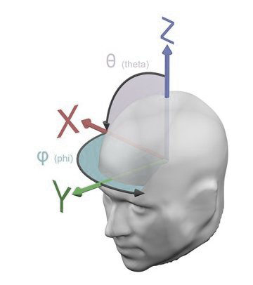
The last three columns contain the sensor positions, specified as
spherical coordinates consisting of the two angles theta and phi
and a
radius rho, with theta and phi measured from the
upward (z) axes as shown in the graph below. Although EMEGS (Qt
versions) displays data on a realistically shaped head model,
sensor
approximation, inverse modeling and similar calculations are
performed
using a spherical head model with the constant default radius of 9
cm
for all sensors. Top]

You can prepare your sensor coordinates in Excel or any other Spreadsheet application and copy and paste the content in a text editor. Save the file as text file with the *.qecfg extension. Make sure to remove trailing empty lines at the end.
EEG configurations and standard MEG configurations are found by
checking a list of possible configuration files for the first
occurence
of the channel number in question. This list is stored in the
study
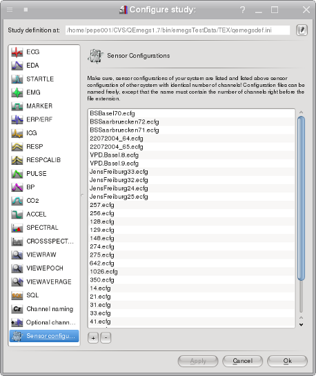
definition of a study folder and can be modified using the configure study dialog:

This list initially
contains a fiew default entries, but you will likely add your own
files
on top of this list. Entries are searched from top to bottom for
the
first file, which contains the correct number of channels right
before
the file extension. In the example above, if you open a data file
with
129 data channels, the file 129.ecfg
will
be used. Sensor configuration files
are loaded from the emegs2dUtil/SensorCfg/-folder
(except
for the case of individual configurations), so
for this example, the sensor configuration file ./emegs2dUtil/SensorCfg/129.ecfg
will be loaded. [Top]
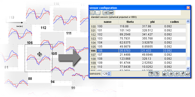
When sensor axes are arranged as planar projection and the arrow selection type is selected, sensor axes can be selected and then dragged to an arbitrary position. 2d-XY-Coordinates are retransformed to sperical coordinates which are updated accordingly on the sensor configuration docking window. Save the thus modified sensor configuration to save changes of the sensor positions for later use. Push the set sensor set button on the sensor configuration docking window to apply the sensor configuration for 3d display. [Top]


For the inidividuel sensor type, the sensor configuration file
must
be named exactly
as
the data file, except for the file extension, which must be *.pmg. Optionally head surface
points can be given in a *.sfp
file, origin coordinates can be given in a *.cot file, both files again
named
as the datafile except the file extension. The *.pmg, *.sfp and *.cot files are standard text
files, as procuded by CTF and BTI MEG systems.
MEG Grand averages can also be loaded with the SCADS sensor format, using an
averaged or default configuration from the /emegs2dUtil/SensorCfg folder.
Please note however, that sensor space regularization may be
necessary
to compensate for the sensor position variance across subjects.[Top]